September, 2023
Derivation of Physically Based Rendering

Physically based rendering (PBR) is a general term for techniques in 3D graphics that approximate physical laws. The term PBR has come to generally mean techniques which aim for realistic rendering of real world materials. The PBR approach developed by Disney in 2012 still forms the basis of real-time rendering of realistic materials. This post explains the physical models and mathematics behind PBR. Hopefully by the end you will have justified why PBR shaders, for example this GLSL shader, look physically correct.
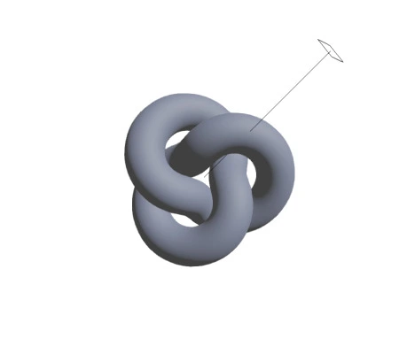
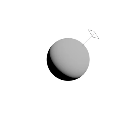
A dielectric (not metallic) material lit by a directional light following a PBR model.
Principles
To realistically render materials in a consistent manner some important laws should be obeyed.
- Conservation of energy, the energy of light hitting a surface is less than or equal to the energy reflected.
- Law of reflection, the incident angle equals the reflected angle for light reflecting off a mirror.
- Fresnel Equations, the proportion of light reflected or transmitted when hitting a surface follows the Fresnel equations.
Accurately simulating all the behaviors of light is infeasible for real-time graphics, various simplifying assumptions about light are made in PBR including:
- Light is always unpolarized.
- Light's wave properties can be ignored (eg. diffraction, interference) and treated as rays, this is called geometry optics.
- Light acts the same going from a light source to viewer as vice versa, called Helmholtz reciprocity.
These assumptions rarely cause problems which are visible, but certain situations or materials can exaggerate errors. For example, when multiple reflections occur between metallic surfaces, accounting for polarization can visibly change the result.
The Model
For each pixel on the screen imagine a ray which travels from a virtual eye and through the pixel's location on the image plane. The ray will eventually hit an object. If the object is opaque (ignoring atmospheric effects) the colour of that pixel will be determined by the light the object scatters from that point towards the pixel. PBR is about calculating the intensity of this scattered light.
Illustration of our physical model.
Radiance and Irradiance
Intensity is an general term, radiance and irradiance are two more specific physical units of light intensity. Radiance and irradiance technically have the same physical units of watts per square metre (
Irradiance
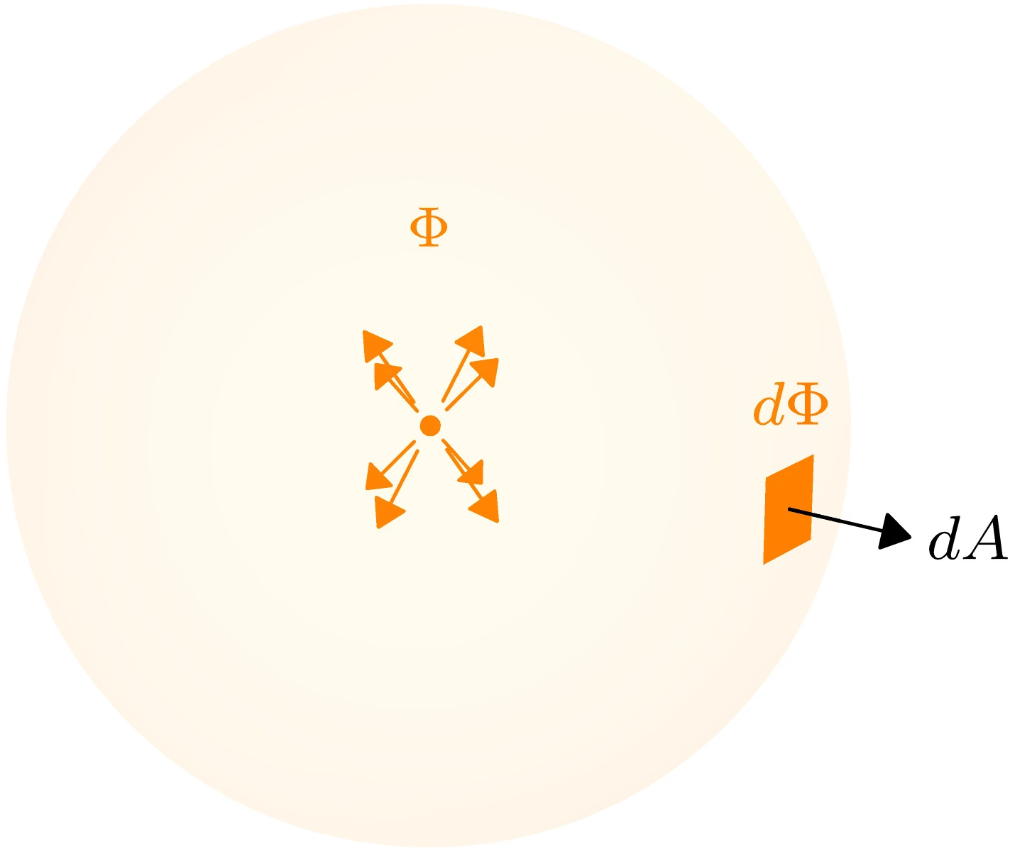
Irradiance is the relative flux through or onto an area.
Imagine a point emitting light in every direction with a total radiant flux of
The notation
Radiance
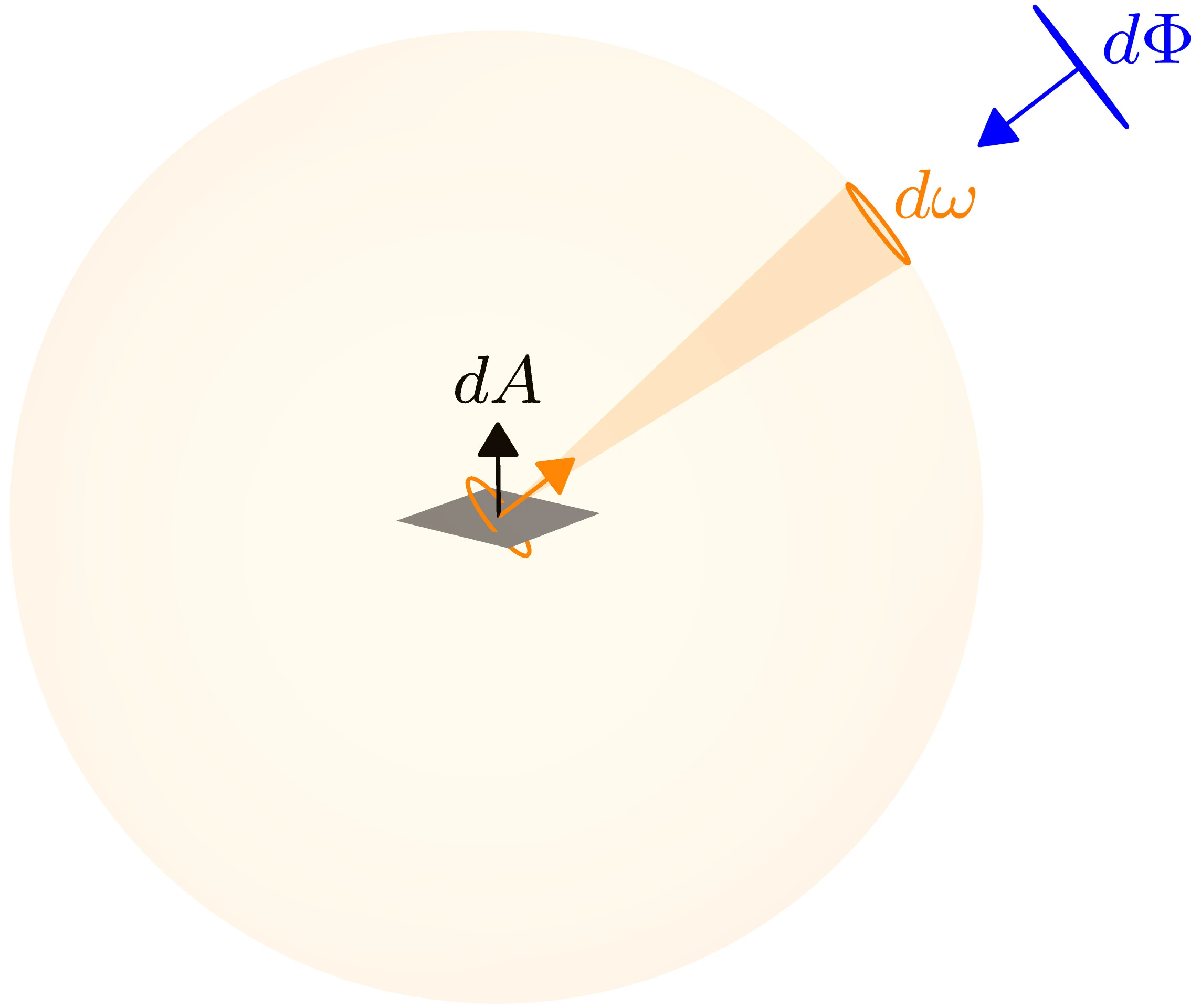
Radiance is the flux from a certain direction onto or reflected from an area.
Irradiance considers flux coming from every direction, but in rendering we want to know the light from a certain direction. Radiance is the directional form of irradiance. Unfortunately, if we looked at the flux from exactly one direction it would always be zero. To resolve this, imagine a unit sphere surrounding our area, we consider all flux which enters through a small "patch"
This patch is analogous to the arc of a circle. The length of an arc is measured in radians, the patch's area is measured in steradians.
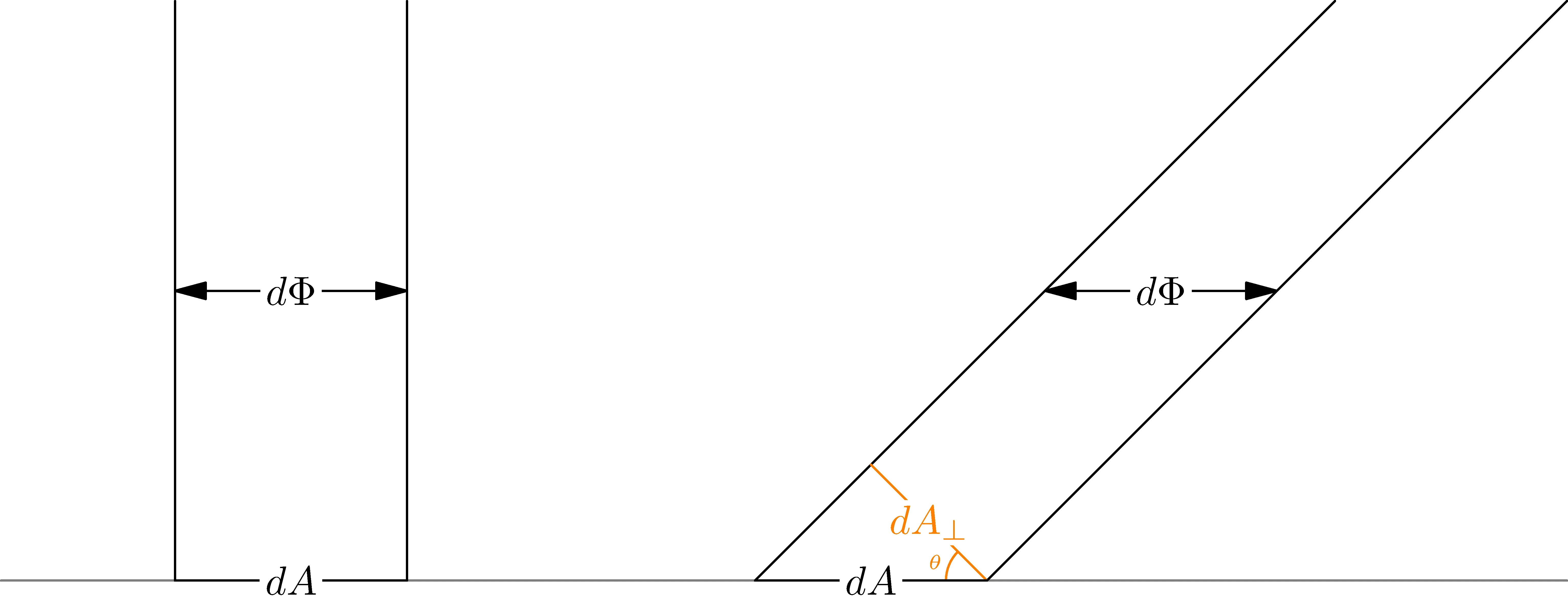
Projecting the area
If the area
Putting together our projected area and the solid angle with the definition of steradians, radiance from a direction
To further explain this definition, just as an arc length is equal to
The reason why radiance is defined for a patch on a sphere is that it makes the radiance of a light source independent of the distance and intrinsic to the light source. This can be illustrating by considering the following, as the distance from a light source increases, the flux into our patch decreases following the inverse square law
We can find irradiance onto an area by adding radiances from all incident directions, which define as
where
Formally, radiance is the radiant flux (
In this post we are going to assume that the radiance
Colour
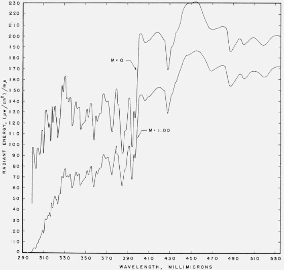
Spectral power distribution of sunlight.
The radiances we deal with will vary with the wavelength (i.e. colour) of the light. We could calculate the radiance for every visible wavelength, called a spectral power distribution (SPD), but this would be very computationally expensive. Luckily, we can approximate the perceived SPD by combining red, green and blue (RGB) radiances. For this reason, consider radiance, and any other spectral quantities, as RGB vectors.
Rendering Equation
If we consider our physical model again, we only care about flux directed towards the pixel from the object. Light from other directions is not focused by a camera's lens or the cornea. The pixel's colour is determined by the radiance scattered towards the pixel from the intersection point with the object's surface.
The light the object scatters towards our eye is either reflected from the surroundings or emitted by the object.
This is called the rendering equation. Materials which emit light have a positive
As mentioned earlier, the point
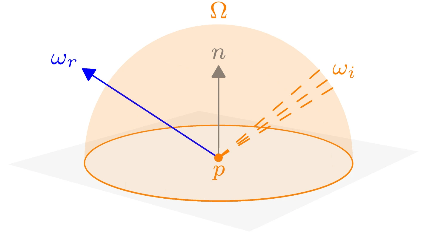
The hemisphere
We are trying to find the reflected radiance
In this article, the notation
You may be wondering why the BRDF is defined in terms of incident irradiance and not radiance, it is so that a BRDF does not vary systematically with light direction. This does not mean the BRDF does not depend on light direction, only that it's directionality is explained by the reflection of the material itself and not by the projection of flux. Another way of thinking about this is that the
BRDF
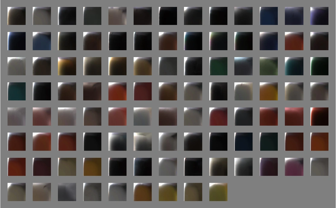
Slices from the BRDFs of different materials showing how reflection varies according to incident direction, from the MERL BRDF dataset.
BRDF is the proportion of radiance reflected towards
Since the BRDF is defined by input irradiance, energy conservation can be guaranteed if the reflected radiances are together less than the incident irradiance. Using the same conversion from radiance to irradiance, this time for the reflected radiances, we can ensure energy conservation if
To satisfy the principle of Helmholtz reciprocity we should also be able to swap incident and reflected directions,
Different materials have different BRDFs which can be measured empirically or calculated from theoretical models. PBR consists of a group of energy conserving BRDFs which are usually derived from the microfacet model. Before deriving and explaining the microfacet BRDF we will derive some simpler BRDFs which will be important later.
Lambertian

The tiny facets of ice crystals in unpacked snow make it close to an ideal lambertian material. "Snowy Hillside, Creag a' Bhealaich, Sutherland" by Andrew Tryon, Creative Commons.
The simplest possible BRDF would be some constant, energy conserving value. This corresponds to a material which reflects light in every direction with equal radiance. A material may only be slightly lambertian, the part of the reflection which is lambertian is called the diffuse reflection.
When light hits a surface we usually think of it bouncing off like a mirror, how does a lambertian material fit into this model? While it's true that some light reflects off a surface like a mirror, this is the specular part of the reflection, some light is also transmitted into the material's surface. For most materials, transmitted light continues to be scattered in the subsurface of the material until it is directed back out, now in a random direction but still close to where it entered. This is diffuse reflection.
Yellow light hits a surface, the green wavelengths are absorbed in the subsurface and the red wavelengths scatter diffusely making the material appear red.
In coloured materials, some wavelengths of light are absorbed by the material in the process of refracting. These wavelengths are removed from the diffuse reflection, giving the material a colour. The diffuse reflection's colour from incident white light is called the albedo of a material.
Since the Lambertian BRDF is uniform we can set
This is the Lambertian BRDF.
Mirror

Mirror ball ornament demonstrating specular reflection, CC0.
Metals, especially highly polished metals, reflect light to produce a mirrored appearance. For now we will consider the case of a perfect mirror which reflects all incident light specularly. Unlike diffuse reflection, specular reflection is usually considered to not have a colour because the light is not absorbed by refracting within the material.
BRDF of a perfect mirror for some specific incident direction.
The law of reflection tells us the reflected light is the incident light flipped about the normal. This means the mirror BRDF should only be positive when the reflection direction
where
Specular Microfacet
If you scratch a metal it becomes less shiny, and polishing makes it more shiny. In scratching the metal we are changing the microscopic surface of the metal to be more rough. A material's microsurface can be very complicated so we make an assumption that materials microsurfaces only vary in one parameter, roughness. We also assume that there are no overhangs in the microsurface.

Microsurface of gypsum, coloured SEM by Steve Gschmeissner.
The microfacet model accounts for roughness by treating our area
Microsurface of a mirror, the roughness is
Microsurface of a rough material, light is reflected in many directions and some reflections are blocked.
If we consider microfacets of every possible orientation and add their contributions we can find the overall BRDF of the macrosurface,
where
Each microfacet has it's own BRDF
Roughness
Roughness is a measure of the microscopic bumpiness, a more rigorous definition is it is the variance in the orientations of the a material's microfacets. Assuming microfacets on average point towards the macronormal, then rougher materials have more micronormals pointing in different directions. The roughness is usually represented by
Microfacet BRDF
If each microfacet is assumed to be mirror-like and has perfect reflectance (
where
The delta function means that rather than having to sum over all incoming light, we only care about light coming from a direction our micronormal can reflect, when
by change of variables.
We now need to find
Substituting back into our energy conservation integral,
The delta function enforcing
Substituting
The overall specular BRDF, made by summing the microfacets, is
Again, the delta function eliminates the integral and enforces
Density Term
A valid density term should both fit this condition and be physically plausible. Since there can't be overhangs, assume if not stated that each distribution is defined to equal
There are different models of rough surfaces, one idea is to consider the height at each point on the surface as following a gaussian distribution with variance set to the roughness parameter
Another model is GGX or the Trowbridge-Reitz distribution proposed by Walter et al.. The GGX distribution better matches empirical measurements of rough material, which have longer tails of steeply angled microfacets than predicted by the Beckmann distribution. The probability distribution is
The GGX distribution is also simpler to calculate. The GGX distribution can be shown to fit our area rule as well:
The distributions presented here assume a constant roughness
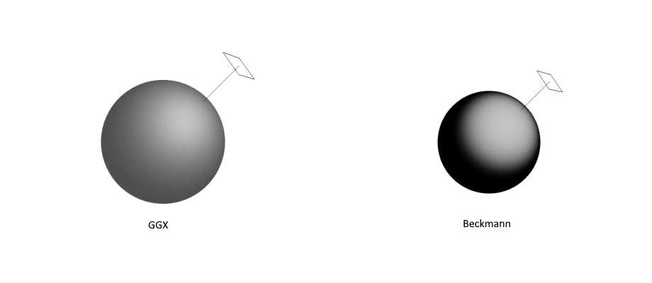
Visualisation of the GGX and Beckmann density functions. For low roughness materials an off-peak bright spot is visible.
Geometry Term
The geometry term defines the proportion of the microfacet surface which is visible from both the incident and reflected directions. Light which would hit a microfacet may be blocked by another part of the surface, this is called shadowing. Alternatively, reflected light may be blocked from the viewer by the surface, called occlusion.
A rough surface which shows both shadowing and occlusion effects.
Since we don't know the actual microsurface, the geometry term tells us the expected degree of occlusion and shadowing for a microfacet distribution.
Smith suggested an approximation for the geometry term
This is an approximation because the visibility is not actually independent, for example a microfacet in a deep V is less visible from both directions. This is called an uncorrelated geometry function, as opposed to correlated.
Smith derived a method to calculate
Alternatively Earl Hammon Jr also suggested a cheap approximation to a correlated geometry term based on ray traced results,
Visualisation of the geometry term, all those presented here look similar.
PBR
Fresnel Equation
In solving our specular microfacet BRDF we assumed that each microfacet was a perfect mirror, but as discussed when deriving the Lambertian BRDF, some of the light is not reflected, but rather scattered inside the material.
Some proportion of the incident energy is transimitted, and some is reflected.
The fresnel equations describe the proportion of incident radiance which is transmitted through a boundary, such as from air to our material.
is commonly used instead, where
A dialetric's
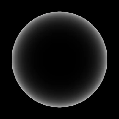
An sphere shaded by the Fresnel-Schlick approximation, grazing angles (light tangent to the surface) cause stronger specular reflections.
Specular and Diffuse
Our final PBR BRDF must combine the specular microfacet with a diffuse reflection. The specular reflection only occurs when light is not transmitted. Using the Fresnel equation where the boundary is oriented towards the microfacets
Light which is not specularly reflected should be diffusely reflected instead. This would require solving our microfacet BRDF again for the case of a Lambertian microfacet BRDF (
has no closed form solution since there is no longer a delta function to eliminate the integral. It is simpler if we ignore the microfacets for the Lambertian and use the macrofacet normal
Our final PBR microfacet BRDF is then
Using the rendering equation, the radiance directed towards the viewer is
This can be solved analytically using IBL or, assuming we only have analytically light sources (eg. directional lights) in our scene, for a set of
Code
The code for direct lighting of a dielectric material with PBR is found below for reference. There are some approximation used which can be found or derived from Edwards et al.. This code is for illustration purposes.
#define M_PI    3.14159265358979323846264338327950288
#define EPSILON 1.19209e-07

uniform float time;

uniform int G2_mode;
uniform int D_mode;
uniform float alpha;
uniform float dir_radiance;
uniform vec3 albedo;
uniform vec3 specular;
uniform vec3 emissive;

varying vec4 p;
varying vec3 n;

vec3 F_Schlick(float cLdotH, vec3 F0) {
  return F0 + (1.0-F0)*pow(1.0 - cLdotH, 5.0);
}

float G2_GGX_corr(float cLdotN, float cVdotN) {
  // Correlated Approximation
  float nom = cLdotN * cVdotN;
  float denom = mix(2.0*nom, cLdotN + cVdotN, alpha) + EPSILON;
  return nom / denom;
}

float G2_GGX_uncorr(float cLdotN, float cVdotN) {
  // Uncorrelated Approximation
  float nom = 4.0 * cLdotN * cVdotN;
  float denom = ((2.0 - alpha)*cLdotN + alpha) * ((2.0 - alpha)*cVdotN + alpha);
  return nom / denom;
}

float G1_Beckmann(float cXdotN) {
  float a = 1.0 / (alpha*sqrt(1.0 / (cXdotN*cXdotN + EPSILON) - 1.0) + EPSILON);
  float a2 = a*a;

  return (a < 1.6) ? ((3.535*a + 2.181*a2) / (1.0 + 2.276*a + 2.577*a2)) : 1.0;
}

float G2_Beckmann_uncorr(float cLdotN, float cVdotN) {
  return G1_Beckmann(cLdotN) * G1_Beckmann(cVdotN);
}

// Derived from Λ = (1 - G1) / G1
float A_Beckmann(float cXdotN) {
  float a = 1.0 / (alpha*sqrt(1.0 / (cXdotN*cXdotN + EPSILON) - 1.0) + EPSILON);
  float a2 = a*a;

  return (a < 1.6) ? ((1.0 - 1.259*a + 0.396*a2) / (3.535*a + 2.181*a2)) : 0.0;
}

// G2 = 1 / (1 + Λ(i) + Λ(r))
float G2_Beckmann_corr(float cLdotN, float cVdotN) {
  return 1.0 / (1.0 + A_Beckmann(cLdotN) + A_Beckmann(cVdotN));
}

float D_Beckmann(float HdotN) {
  float a2 = alpha*alpha;
  float c2 = HdotN*HdotN;

  float t2 = 1.0/(c2+EPSILON) - 1.0;
  float nom = exp(-t2/a2);
  float denom = M_PI*a2*c2*c2 + EPSILON;
  return nom / denom;
}

float D_GGX(float HdotN) {
  float a2 = alpha*alpha;
  float c2 = HdotN*HdotN;

  float nom = a2;
  float denom = M_PI*(c2 * (a2 - 1.0) + 1.0)*(c2 * (a2 - 1.0) + 1.0);
  return nom / denom;
}

vec3 L_r(vec3 N, vec3 V, float cVdotN, vec3 L, float radiance) {
    vec3 H = normalize(V + L);
    float cLdotN = max(dot(L,N),0.0);
    float cLdotH = max(dot(L,H),0.0);
    float HdotN = dot(H,N);

    vec3 F = F_Schlick(cLdotH, specular);
    float D = D_GGX(HdotN);
    float G2 = G2_GGX_corr(cLdotN, cVdotN);

    vec3 brdf_s = F*D*G2 / (4.0 * cLdotN * cVdotN + EPSILON);
    vec3 brdf_d = (1.0 - F) * albedo / M_PI;

    return (brdf_s + brdf_d)*radiance*cLdotN;
}
Further Reading
- Nayer et al. developed a microfacet model for diffuse reflection which is more accurate than the Lambertian used here.
- Walter et al. applied the microfacet model to refraction in transparent materials.
- Sébastien Lagarde's memo has a Mathematica notebook which is helpful for understanding the Fresnel equation and it's approximations (link).